 RaiseUp
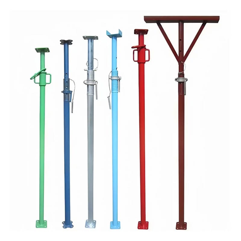
Shoring is temporary structure that holds something up while the permanent structure cannot yet hold itself. Get it right and nobody notices. Get it wrong and the failure is fast, loud and expensive — a slab drops 40 mm, cracks run through the pour, and the remedial conversation starts before the concrete has cured.
Three families, three jobs
Slab shoring towers (falsework). A grid of props, ledgers and jacks under a slab or beam. Used for every cast-in-place slab. Load per leg is typically 10–25 kN; the design work is in the grid spacing, not in the prop itself.
Trench and excavation shoring. Steel plates, walers and screw struts holding trench walls. The load is soil pressure, which is a different animal: it is not uniform, it changes with water content, and it can double after rain.
Hydraulic shores. Adjustable struts with a pump port, used for propping openings, lifting loads and emergency stabilisation. Fast to install, but they hold a load only as long as the hydraulic circuit is intact — always fit the mechanical lock.
| Type | Typical load | Setup time | Reuse cycles |
|---|---|---|---|
| Slab shoring tower | 10–25 kN per leg | 20–30 min per bay | 100+ |
| Trench shoring panel | 30–60 kN/m² soil | 15 min per panel | 50–100 |
| Hydraulic shore | 5–50 kN | 2 min per unit | 20–50 |
What the components actually do
- Prop (telescopic or adjustable): carries axial load. Capacity falls sharply with extension — a prop rated 20 kN at 2.0 m may be rated 12 kN at 3.5 m. Always select on the extended height, never on the catalogue maximum.
- Ledger / horizontal member: ties props together so they cannot buckle sideways. Without ledgers a prop is a column with an unknown effective length.
- Jack base and U-head: transfer load and allow height adjustment. The U-head must capture the bearer; a bearer sitting loose in a U-head is a slip waiting to happen.
- Tripod / stabiliser: stops a lone prop from falling before the frame is complete. Cheap insurance for a very common accident.
Load path, in order
Slab weight → formwork → bearers → U-head → prop → jack base → sole plate → ground. Every one of those steps needs a bearing surface. Failures usually happen at the two ends: a sole plate too small for the ground bearing capacity, or a U-head that is not actually under the bearer.
For a 200 mm slab the design load is roughly 6.0–6.5 kN/m² including formwork and live load. At 1.2 m spacing that is about 9 kN per prop — well inside a 20 kN prop at short extension, and inside a 12–15 kN prop at medium extension. If your numbers land near the limit, widen the grid rather than adding props randomly: a shoring tower with uneven spacing loads the tight bays first.
Safety checks before loading
- Sole plates on every leg, sized for the ground. On slab-on-grade, 150 × 150 mm minimum; on compacted fill, bigger.
- Props plumb within 1:200. Lean props buckle early.
- Ledgers at every 1.5 m of height, and in both directions on towers.
- Pins and locking devices fully engaged on every telescopic section.
- No props bearing on a suspended slab without a back-propping plan — the slab below is a structure too.
- Documented inspection before the pour, signed by the person who will be blamed if it fails.
Why steel instead of timber
Steel props hold their capacity after 100 cycles, do not shrink with moisture, and can be inspected for damage in seconds. Timber shoring is competitive only for one-off, low-load work where transport cost dominates. For export projects the deciding factor is usually container volume: a 40 ft container carries roughly 900–1,100 steel props, which is enough falsework for a mid-rise floor plate.
We supply adjustable steel props, telescopic props and complete shoring support frames with load certificates per batch. Send your slab thickness, floor height and prop grid and we will confirm the rating at the extension you actually need.